by ARNE BATTERMANN
In order to obtain reliable measurements, several surveys have been performed in Judayta village and at Judayta pumping station. The following section shall give an overview on these surveys. The importance of some particular problems will also be discussed. Section 5.1 describes the bucket fill test at the well production of Judayta pumping station. In section 5.2 domestic water meters are tested on accuracy under the influence of intermittent supply.
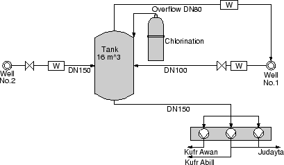
The pumping station of Judayta takes water from two wells (appendix
18). These wells are feeding a storage tank of
app. 16 m3 . Each well is producing app. 80
![]() .
Normally only one well is running, while horizontal pumps take the
water from the tank to supply the villages. An automatic control for
avoiding overflow does not exist.
.
Normally only one well is running, while horizontal pumps take the
water from the tank to supply the villages. An automatic control for
avoiding overflow does not exist.
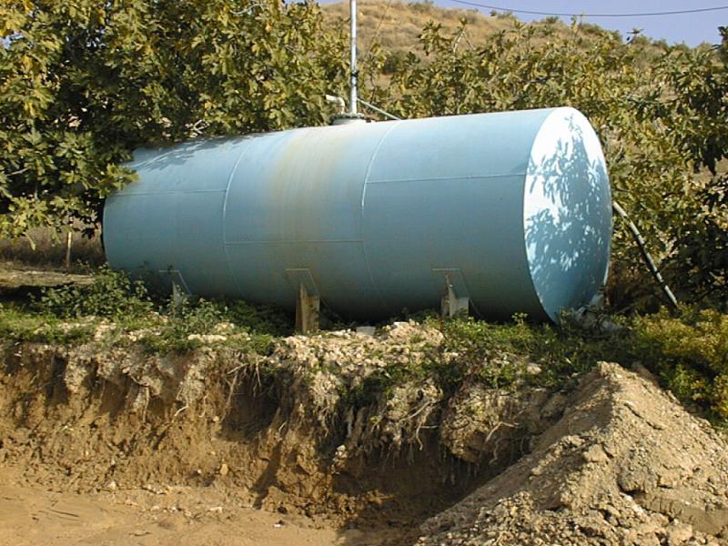
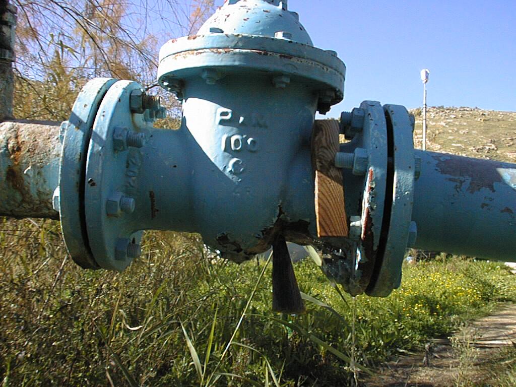
In figure 8 the tank of the pumping station is shown. The picture shows the erosion that takes place when the tank is overflowing at a rate that could not transported be by the DN 80 pipeline going back to the well.
Currently the overflow of the tank goes back into one of the wells (figure 9). Another disadvantage of the current situation is that the chlorination is leading into the tank, which means that the back flow into the well is chlorinated.
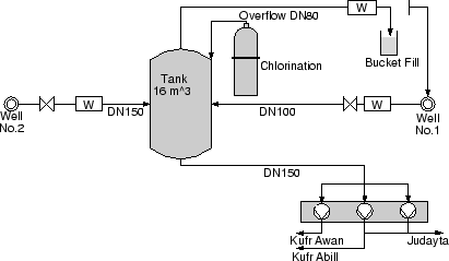
During several visits at the pumping station the overflow was running and the pipe was approximately three-quarter filled. A water meter is installed by the Water Authority. However, the meter readings are not accurate, as the pipe is not filled completely, caused by free surface flow, while the water meter requires pressurized flow. The "bucket fill"- test was chosen to control the water meter readings. The water meter has been out of order two weeks after its installation.
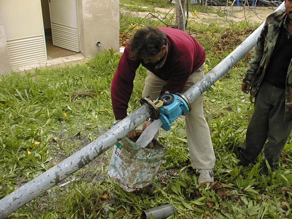
On 19th, January 2001 the water meter on the DN80 pipe from the tank to the well has been taken off. Several tests of filling a bucket of 14 l at the opened pipe (figure 10) have been made and the time of filling has been recorded.
Figure 11 shows the bucket fill taking place. The bucket was the best that could be found on site.
During all tests the bucket is filled in app. 4 seconds:
Q = ![]() . 3600
. 3600![]() = 12600
= 12600![]() = 12.6
= 12.6![]()
At the time of the test, the water meter at the overflow showed a
flow of 0.3
![]() :
:
Q = 0.3![]() . 60
. 60![]() = 18
= 18![]()
This means, that the water meter reading is wrong by 70 %.
Figure 12 shows a repair attempt of the water meter at Judayta well No.1.
At the time of these tests one well was working with a production
of app. 90
![]() . With taking the result of the
bucket fill as average back flow, a percentage of 11% of the produced
water is running back into the well.
. With taking the result of the
bucket fill as average back flow, a percentage of 11% of the produced
water is running back into the well.
This means that the well efficiency is reduced by 10% at some times. The total amount of back flow is hard to estimate with the current water meter setup at the pumping station.
Meanings to solve the overflow problem are described in section 9.2.
It is not possible to use the term unaccounted-for water in this case. In section 2 is defined that ``[...] losses occurring between raw water extraction and input into the distribution system are not considered unaccounted-for water''.
With intermittent water supply, air is sucked and pushed in reliance with the status of supply period because of empty running pipes. At the beginning of a supply period the air is pressed upward by the water filling the pipe and in the end of the period air should be sucked as a consequence of empty running pipes. The sucked air could turn back the domestic water meters and cause an enhancement of unaccounted-for water.
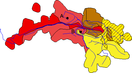
Two locations were chosen for examining the reaction of the domestic water meters on air in the network. Both locations (A and B) have an elevation of app. 270 m above pumping station (573 m aSL) shown in figure 13. The domestic meters have been tested over two supply cycles (two weekends).
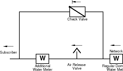
The installed arrangement consists of a check valve, an additional water meter and an air release valve (figure 14). The check valve is installed on a bypass parallel to the regular pipe. The air release valve is fitted behind the domestic water meter and another water meter is installed additionally behind the air release valve.
During the filling period water is flowing over the domestic water meter, which is recording the billed quantity of water. During the supply the bypass is closed due to the check valve. The air escapes over the air release valve and the additional water meter behind is counting the unadulterated quantity of water flowing to the customer.
After changing the valve settings in Judayta for supplying another zone, the feeding pipe is closed app. 20 m below the tested domestic water meter. After this, the pipeline will empty into the lower tanks of the supply zone. The pipeline might run empty because of leakage also. Air is sucked through the inlets of the customer tanks, which stay opened.
The measurement of the additional water meter remains unchanged because the air is sucked through the air release valve or the bypass. The back flow is recorded by the regular water meter.
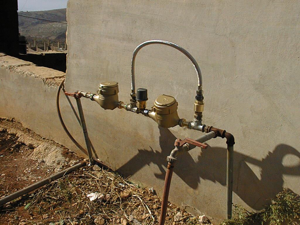
Figure 16 shows a photography of the fitting installation including the air release valve and the two water meters.
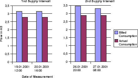
The expected shortfalls in receipts can not be confirmed. Exactly the opposite happens in three of four cases. Three times the additional water meter counted less than the domestic water meter.
In Figure 17 a difference between the billed and actual consumption of 11 - 16% becomes obvious. This means that the billed consumption might be higher than the actual consumption by the subscriber.
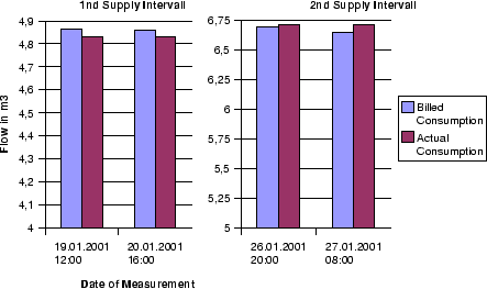
In Figure 18 the difference between billed and actual consumption is not comparable to the difference at location A, but the tendency exists during the first supply interval. During the second interval the actual consumption is slightly higher than the billed consumption.
The span between the actual and billed consumption might depend on the location, the behaviour of the consumer or sudden pressure drops.
If all the consumers open their tanks before starting the supply, the mistake by pushed air at the consumer on a high elevation is lower, because the air escapes at the customers below also. This should be the actual situation because each customer is opening his tank in time to get as much water as possible.
In case the customers below open their tanks lately the mistake at the subscribers above is getting adequately bigger.
The mistake of sucked air should decrease with an increasing pressure difference between closed valve and domestic water meter. If the water meter is close to the valve which setting is changed for supplying another zone, the connected pipe main is full of water for a longer time than at a higher house connection, where back flow of air is happening soon.
The survey results clearly show, that the quality of domestic water meter readings in intermittent supply areas is limited even if the water meters are calibrated and the personnel for the readings is reliable. For a better measurement of domestic consumption, installations of air release valves are an opportunity.
However from the perspective of the water undertaking in this case accurate readings are not desired for the following reasons: